Loading...
Categories
June 2026 Vair Views
Loading...
Loading...
Loading...
Loading...
Loading...
Loading...
Loading...
Here’s a great video of Gene’s beautiful V8 Corvair on You Tube!
Loading...
Loading...
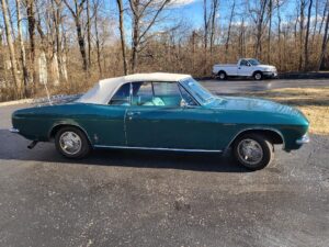
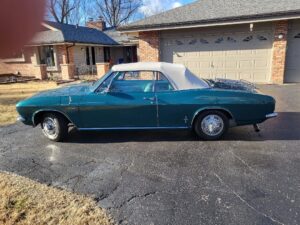
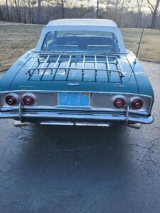
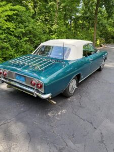
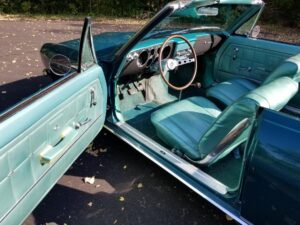
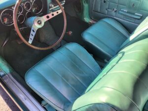
I am moving to a home on a gravel road, and just don’t want my ’66 to get ruined by driving on it.
It’s a great looker and suitable for a daily driver. The engine was sourced from Bret Starostki and had new seals/gaskets installed by Kent Goddard and Trevor Monninger.
The price is $15,000. Please call or email me for more information and pictures. I hate to let this go.
Kurt Arthur
nyuk3-corvair@yahoo.com
314.503.4959